Project Baja Foz!

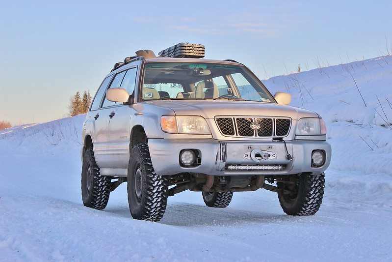
Hey everyone, this is the new build for The Wandering Foz, continuing where the old thread left off: The Great Alaskan Tundra Humper

IMG_3756 by jeremiah stewart, on Flickr

Goal:
I have wanted to race the Baja 1000 since I was a little kid, but a few years ago I came across the Mexican 1000 which is a little more grassroots and easier for a normal guy like me to race in. So that's the goal! I wanted to race in their "Rally Raid AWD" class using my Hotbits coilovers as they were at the max travel for that class, but most years there is nobody in that class. Might as well try to be competitive if i'm entering a race right? So the class I'm shooting for is Score Class 7 or BITD 7200. In the Mexican 1k it'll either be "Heavy Metal Class" or "Pre-run Truck".

For now I will only be focusing on suspension so I can stay on track to be able to take the foz on a roadtrip planned for May 2017. A roll cage and a bunch of safety items will need to be built after the roadtrip unless I have the time to do the rollcage this winter. Shooting to make the race in the spring of 2018, but if the foz is ready sooner than then, then I will enter a domestic race to get my feet wet.

Plan:
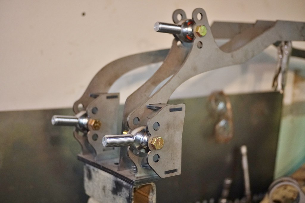
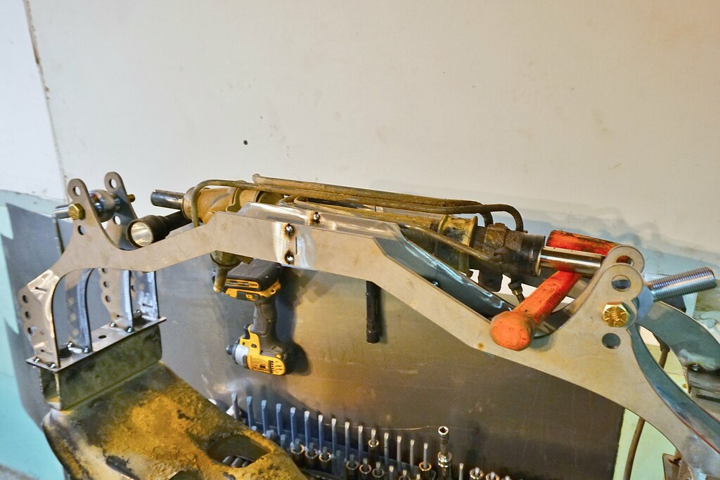
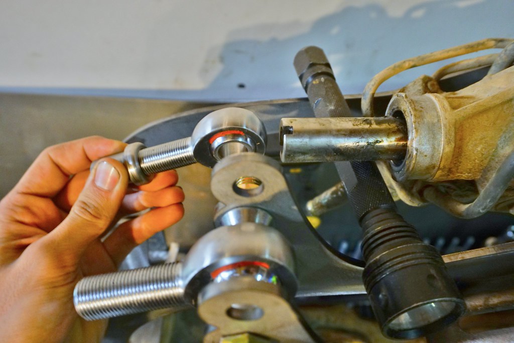
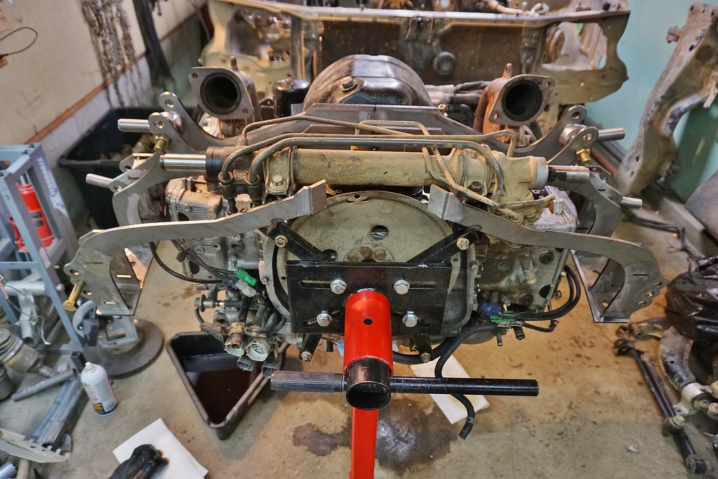
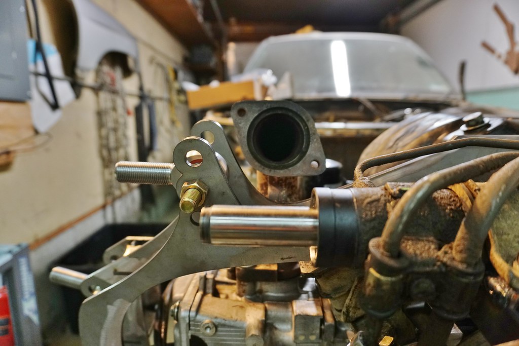
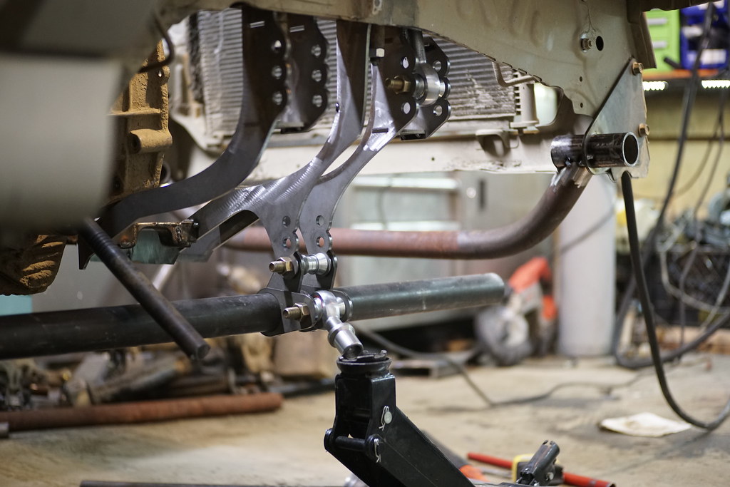
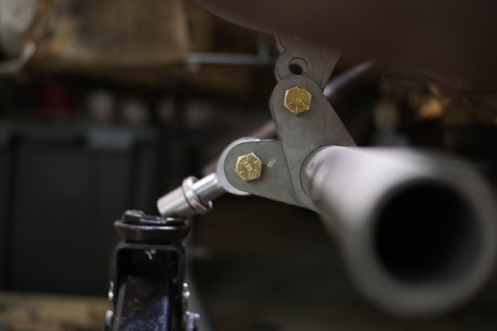
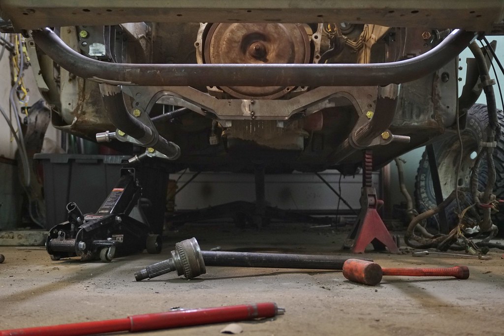
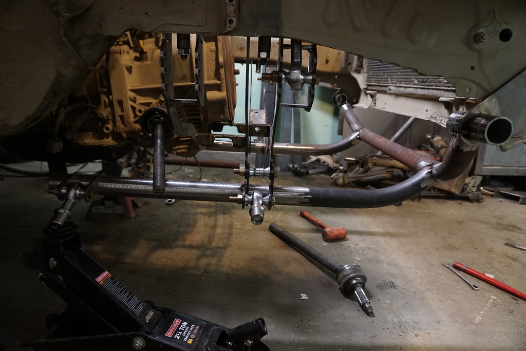
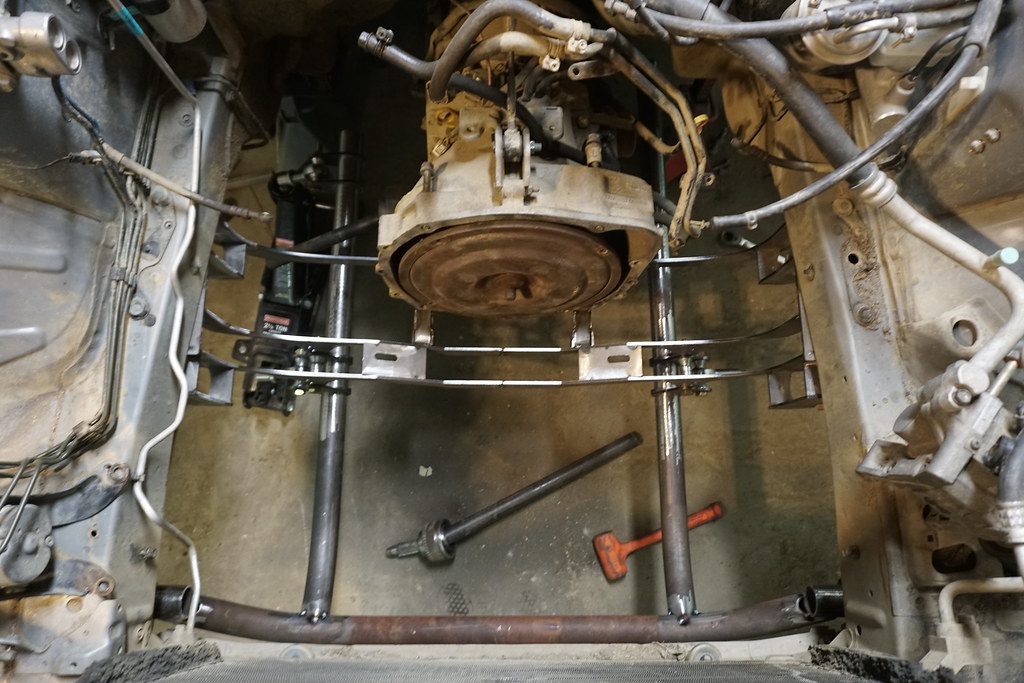
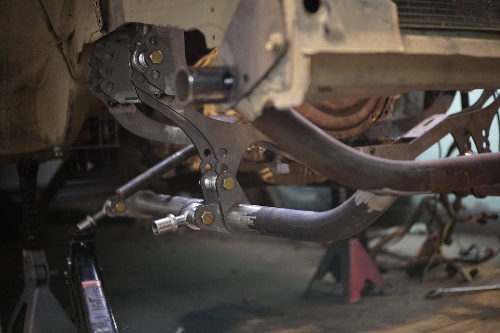
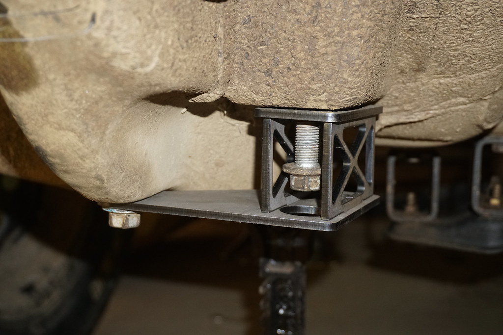
  • Dual A-arm front suspension cycling 18-22" of travel
  • Dual A-arm rear suspension with toe link (will make sense later - similar to the PPI 015 Toyota) cycling 20-24" of travel
  • 32" tires on factory offset wheels to allow for longer arms and more travel while keeping it under the BITD max width of 85"
  • Either King or Fox internal bypass coilovers all around
  • High compression EG33 unless the length is more than I want to build around, then it'll be an EZ30
  • Extended length axles (+8") probably from DSS

Follow on Instagram:@thewanderingfoz
 
Got all of my heim joints in, as well as all of the pieces that I drew on CAD and got from Anderson Design and Fab

DSC00408 by jeremiah stewart, on Flickr

DSC00411 by jeremiah stewart, on Flickr

DSC00423 by jeremiah stewart, on Flickr


Started on the front subframe, using the old subframe as a jig:


DSC00421 by jeremiah stewart, on Flickr

DSC00419 by jeremiah stewart, on Flickr

Need to start boxing it in and reinforcing it, then get it under the car to tie it into my other mounts.

Below is my crazy ball joint replacement idea, let's hope it works out. The big hole is to hold a uniball joint, which I am still waiting on. I may need to just fab a whole knuckle for more strength though, we'll see.


DSC00414 by jeremiah stewart, on Flickr

DSC00415 by jeremiah stewart, on Flickr


The upper and lower joints will be 1" uniball joints, probably overkill.
 
You'r doing something where i'm dreaming of!

have you seen bajaburu on facebook? That is a guy who builded and raced a wicked long travel suspension impreza in the the baja 1000.

Keep us informed!
 
I'm glad you guy guys are excited, keeps me motivated when I feel lazy :D

I made some good progress yesterday, but got cut short by having to go pickup an engine block for mockup.
So I started off by bolting the subframe in to mockup the knuckle and make sure everything was gonna work before I started boxing it in:

DSC00499 by jeremiah stewart, on Flickr

DSC00500 by jeremiah stewart, on Flickr

Measured the track width from the center of the subframe, 42.5" then moved the tire inward 2 inches to 40.5" to give me room in the future for 32x11.5 tires with an inch for wheel offset differences. This will be the stance with stock fenders:

DSC00533 by jeremiah stewart, on Flickr

Bolted the knuckle into a wheel as well:

DSC00544 by jeremiah stewart, on Flickr

DSC00545 by jeremiah stewart, on Flickr

There's about 1/2" clearance all around in a 15" wheel, pretty good. Most likely going to be running 16's anyway.

Mocked up the steering rack location:

DSC00534 by jeremiah stewart, on Flickr

Looks like the inner heims are going to stick out just past the LCA pivot after the clevis is bolted on, so I may see some bump steer, but it looks like if I play my cards right, I can mount the LCA down one hole (UP in the pic) and then the inner tie rod heim would be in-line with the LCA and UCA pivots. So either way, we should have very minimal bump steer:

DSC00535 by jeremiah stewart, on Flickr

So I cut the original mounts out of the old subframe to save time, and welded them in the new subframe, and plated them a bit:

DSC00537 by jeremiah stewart, on Flickr

DSC00538 by jeremiah stewart, on Flickr

Mounted:

DSC00539 by jeremiah stewart, on Flickr

Fits like factory (the true test will be to see if the steering shaft fits right up like it did...)

DSC00541 by jeremiah stewart, on Flickr

View from wheel well:

DSC00543 by jeremiah stewart, on Flickr

And lastly, I just need to add these gussets:

Changes by jeremiah stewart, on Flickr

I made the shape the way it is to give clearance for the exhaust and the cylinder heads, but made way more than is necessary which would cause this thing to fold up the first time i landed a jump off-kilter. So anyways, that's the progress so far! My uniball's finally shipped out, so next weekend I may have some control arms mocked up! That's the exciting bit :D
 
Very nice !

From what I see, you will have 2 upper arms and 1 lower arm, right ?
 
Gotta love this level of enthusiasm and DIY competence. Amazing job. Thanks for sharing this unique experience!
 
Very nice !

From what I see, you will have 2 upper arms and 1 lower arm, right ?

Not quite. The upper two mounts are for an A arm, and the bottom mount is the front mount for the lower A arm. The rear mount will be pretty close to the factory location.

Dude. This is insane. Super awesome man keep it coming.

Gotta love this level of enthusiasm and DIY competence. Amazing job. Thanks for sharing this unique experience!

Thanks so much guys! Really appreciate it.

Latest news is that the uniball joints came in, so I tacked two of the cups into the knuckle i've been using for mockup:

DSC00569 by jeremiah stewart, on Flickr

But the bad thing is that the none of the local steel places have the DOM I need, and Amazon doesn't offer it via Prime anymore -lol- so it's going to be about 2.5 weeks until I have the tubing, which is when I'll be in Wyoming for Christmas. Probably should've checked that out a long time ago lol. Time to work on the wire harnesses I guess.
 
Small Update:

I got the engine over to my garage this weekend and test fit the subframe on it to start beefing it up. But first, for those that don't know anything about the engine, it's an EG33 out of a 1992 Subaru SVX. I had it bored out to 98mm (raised displacement by about .6 liters) to fit the forged 11:1CR pistons from JE Pistons. The crank and rod bearings are by King. Also, I deleted the EGR system.


Subframe bolted under it:

DSC00620 by jeremiah stewart, on Flickr

Clearances look great, I have a lot of room for strengthening, keeping in mind engine movement of course:

DSC00621 by jeremiah stewart, on Flickr

DSC00622 by jeremiah stewart, on Flickr

Upside down:

DSC00623 by jeremiah stewart, on Flickr

This shows why I shaped the subframe the way I did, for the exhaust:

DSC00624 by jeremiah stewart, on Flickr

But I don't like how low the exhaust will be since I was shooting for about 4-5" of ground clearance to the subframe at full bump. The exhaust would have like an inch like this, so i'll be building some weird headers later on. Oh, and I've got 20ft of 1.25" DOM on the way which should be way more than enough to do all of the control arms, so once I get back from vacation I'll need to get my **** in gear.
 
So i started on control arms this last weekend, but just in the nick of time before I really made anything, I came across vsusp.com and decided I might as well plug in my numbers and see what I'm working with. It appeared to be limited to about 14inches of travel due to the camber going -20 degrees at full bump, and the upper arm being too short to get enough droop travel. So apparently my initial mock up was crap lol. But I've determined that if I move the upper heims inward 1.5" (can't go further due to valve cover position) and the lower mount down 2" and outward 1.5", I get what looks to be pretty good geometry:
Camber at full droop: -2*
Camber at ride height: -2*
Camber at full bump: -10*
KPI looks good at about 14*, giving a scrub radius of .58" with 32" tires. So I didn't do too bad on the knuckles, and if I can ever get the gearing for it, going to 33" or 35" tires, the scrub radius only improves.
Actual lateral tire scrub I'm unsure about, but from ride height to bump looks very minimal.
Only other things to account for are CV's and tie rod ends, the latter of which I have a lot of freedom with on the knuckle end, and the rack end can be adjusted to put the heims inline with the upper and lower mounts. As for the axles: I'm unsure right now about how much plunge the front axles will have, but I'm planning on running factory style inner joints which have about 2" of throw, and I'm sure it'll be much less than that. Plus the lateral location of the inner cv joint can be adjusted to put it inline with the upper and lower joints as well which might help. On the knuckle, I tried to get the joint inline with the uniballs so that there is no steering plunge.


So after running through a bunch of different ways in my mind to relocate the lower mounts, I came to the conclusion that there was no good way to do it and not have it look like crap. Generally my philosophy is "don't get it right, get it running" but I'm really shooting for the opposite this time around. So after wasting time trying to change the subframe, I started on a better way.

I used some of my tube tabs to hold this piece of DOM in place, with a heim mounted to the tube with two other tabs:

DSC00872 by jeremiah stewart, on Flickr

This allowed me to get the lower joint moved down 2" and over 1.25" like i need (the subframe will not be permanently connected to the tubing like this):

DSC00869 by jeremiah stewart, on Flickr

Then I bent the tip up to mate to a bar I installed that welds to my mounts that bolt to the factory tow hook spot, which is one of the strongest areas in front of the subframe. This will later be where I build my bumper and skid plate off of:

DSC00874 by jeremiah stewart, on Flickr

DSC00876 by jeremiah stewart, on Flickr

DSC00875 by jeremiah stewart, on Flickr

You can see the piece of tubing sticking out of the tow hook mount here, which will be where I can send tubing to the front for the bumper:

DSC00873 by jeremiah stewart, on Flickr

So now I've got a much more solid frame for the control arms to mount to, and will be perfect for bolting skid plates to. I'll be adding some smaller tubing in X's for strength as well. The whole thing will extend to the tailshaft of the transmission and will be mounted to the body in 8 places: front tow hooks, subframe mount, rear factory control arm bushing mount (see below), and the transmission mount spots. So basically the whole front half of the car will be tied together. I haven't decided yet how i'll do the upper arm mounts. I may re drill the holes to move the heim inward 1.5" then just run 1"DOM from the bottom of those mounts to the lower piece of DOM. But I don't think it'll look great. Might ditch the subframe i made and replace with 1" DOM.

This is my mount that takes the place of factory rear control arm mount:

DSC00570 by jeremiah stewart, on Flickr
 
absolutely, absolutely, absolutely awesome!

What kind of gearbox are you planning to use?

Thanks man! I'm going to be running the factory Phase 2 auto with 4.44 diffs. I am not a fan of manual subies off road. I'm also considering going with a phase 1 4eat and putting on a full manual valve body from a nissan skyline (RE4R01A-3A is valve body number) so that I can have instant shifts, engine braking in every gear and the ability to hold any gear.
 
Thanks man! I'm going to be running the factory Phase 2 auto with 4.44 diffs. I am not a fan of manual subies off road. I'm also considering going with a phase 1 4eat and putting on a full manual valve body from a nissan skyline (RE4R01A-3A is valve body number) so that I can have instant shifts, engine braking in every gear and the ability to hold any gear.

Do you keep the oem MPT 4EAT or do you upgrade to the VTD ?
 
Back
Top